
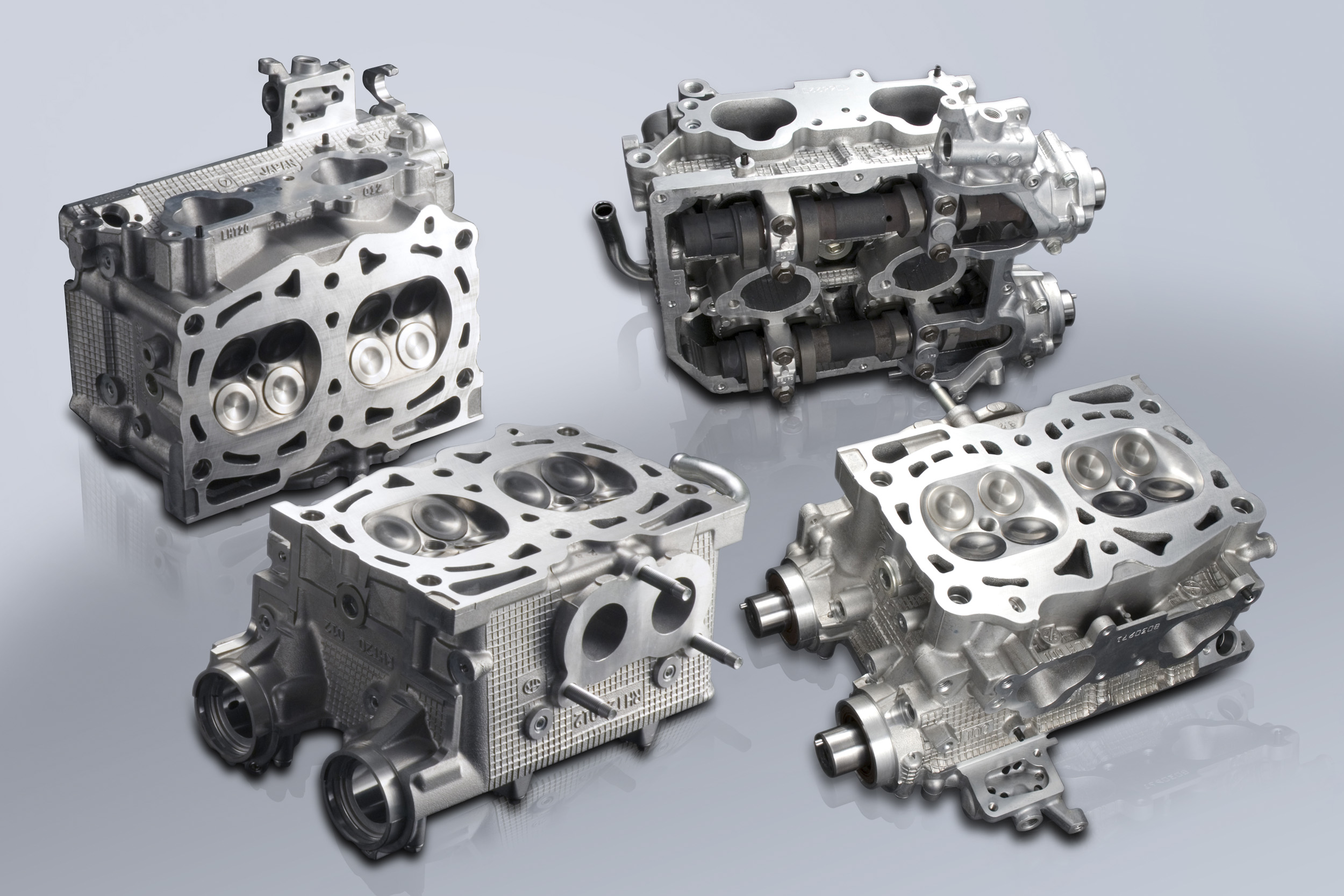
コンプリートヘッド EJCOMPLETE HEAD for EJ
コンプリートヘッド EJ
コンプリートエンジン
高回転・高出力。それらをめざし、対応するために不可欠なパーツ群とヘッドチューニング。
PRODUCT INFO
| 適用 | タイプ | 品名 | 品番 | 定価 | 備考 | |
|---|---|---|---|---|---|---|
| EJ207/20Y | GDB C-G | カムシャフト無 | CPH-EJ20-S | 234012 | ¥780,000 (税込 ¥858,000) | |
| カムシャフト有 | CPH-EJ20-S-C | 234112 | ¥930,000 (税込 ¥1,023,000) | |||
| GR/GV/VAB | カムシャフト無 | CPH-EJ20-D | 234022 | ¥780,000 (税込 ¥858,000) | ||
| カムシャフト有 | CPH-EJ20-D-C | 234122 | ¥930,000 (税込 ¥1,023,000) | |||
| EJ25 | シングルAVCS (北米仕様) | カムシャフト無 | CPH-EJ25-S | 234032 | ¥780,000 (税込 ¥858,000) | |
| カムシャフト有 | CPH-EJ25-S-C | 234132 | ¥930,000 (税込 ¥1,023,000) | |||
| デュアルAVCS | カムシャフト無 | CPH-EJ25-D | 234042 | ¥780,000 (税込 ¥858,000) | ||
| カムシャフト有 | CPH-EJ25-D-C | 234142 | ¥930,000 (税込 ¥1,023,000) | |||
FEATURE / SPEC
| タイプTYPE | カムシャフト無With out camshaft | カムシャフト有With camshaft | ||||
|---|---|---|---|---|---|---|
| 品番P/N | 234012/234022 | 234032/234042 | 234112 | 234122 | 234132 | 234142 |
| ベースエンジン型式BASE ENGINE | EJ25 | EJ207 | EJ207/20Y | EJ257 | EJ25 | |
| 約50.0ccapprox.50.0cc | 約52.5ccapprox.52.5cc | 約50.0ccapprox.50.0cc | 約52.5ccapprox.52.5cc | |||
| バルブVALVE | ||||||
| バルブスプリングVALVE SPRING | ||||||
| バルブスプリングリテーナーVALVE SPRING RETAINER | ||||||
| バルブスプリングシートVALVE SPRING SHEET | ||||||
| バルブガイドVALVE GUIDE | ||||||
| バルブシートリングVALVE SHEET RING | ||||||
| カムシャフトCAM SHAFT | TOMEI IN 250-9.60 EX 256-9.80 S-AVCS |
TOMEI IN 260-9.80 EX 256-10.80 D-AVCS |
TOMEI IN 260-9.80 EX 264-10.00 S-AVCS |
TOMEI IN 260-9.80 EX 264-10.00 D-AVCS |
||
| バルブリフターVALVE LIFTER | STD | |||||
概要Overview
実施する精密加工BUILD PROCESS
1:バルブガイド入替え1:VALVE GUIDE REPLACEMENT
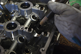 |
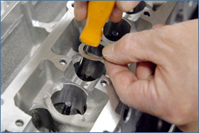
純正バルブガイドを抜くために、シリンダーヘッドを約200度まで加熱します。 アルミ合金製のシリンダーヘッド と焼結合金製の純正バルブガイドの熱膨張率の差を利用することで、純正バルブガイドを抜きます。 TOMEIバ ルブガイドを挿入する際もシリンダーヘッドを同様に加熱し、さらにバルブガイドを液体窒素で約-200度まで 冷却し、この400度近い温度差による材質の熱膨張率の差を利用しセットします。 もし、液体窒素を使用せず、 充分な温度差と膨張差を得られないまま無理に挿入すると、バルブガイドの穴を傷つけたり、バルブガイド自 体が変形し、オイル下がりや、クリアランス不足によるバルブの焼き付きを招きます。 The cylinder head is heated up 200℃ so that the stock valve guides can be removed. The cylinder heads that are made from aluminum alloy when heaated expands more than the materials that the valve guides are made from thus making it easy to remove when heated. The TOMEI Valve guides are also inserted in the same way but the Valve Guides are frozen in liquid nitrogen with to bring down the valve guides temperatures to -200℃ and with 400℃ difference it is then made possible to insert the new Valve guides into the Cylinder Head with ease and safely. If liquid nitrogen is not used then damage can be caused during the removaland re-instrallation of the valve guides as the gap will not be wide enough to fit the new valve guides into the head. This can also cause the deformation of the valve and create gaps which can lead to oil leaks. |
2:バルブシートリング内径拡大2:VALVE SEAT RING INTERNAL DIAMETER ENLARGEMENT
 |
オーバーサイズバルブの採用に合わせ、バルブシートリングの内径を拡大します。 ただ単純にバルブ径に合 わせて拡大するのではなく、オーバーサイズバルブで得た有効吸排気面積を損なうことなく吸排気ポートにスムースにつなげ、吸排気の流れを考慮した角度を採用しています。 また、強度の維持にも留意した仕上げを行っています。 The inner diameter of the valve seat ring is enlarged to accommodate for the oversized valve. There is much more involved than just simply enlarging the valve size and the ring seats. Much consideration in redesigning and experience is vital so not to risk weakening the structure and or hindering performance. It us also involved to the aerodynamics of the untake and exhausts ports with all angles and flow dynamics taken into consideration. |
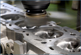
3:バルブシートカット3:VALVE SEAT CUT
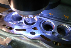 |
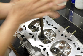
バルブ当たり面の幅・位置・テーパー角度などをバルブ・燃焼室形状・ポート形状に合わせた最適な形に整えます。 これによりバルブとバルブシート間の密着性を上げ、圧縮圧力が逃げるのを防ぎます。 この加 工は エンジン機 種それぞれに燃 焼 室・バルブ・ポートのサイズ・形状が異なるため、それぞれに膨大なテストを実施し、最適な形状を導き出しました。 Each valves seat width,position,taper angle and the surface condition is addressed to maximize the aerodynamics of the mouth from the ports & valve tothe combustion chamber and back to the exhaust port. Each seat is cut to suit each valves position,tapered angle with all surface angles arranged to optimize port flow to the valve and to the combustion camber. By increasing the sealing properties of the valve to the valve seat than more accurate compression can be maintained from preventing any pressure from escaping through any gaps. This process is extremely time consuming to find the optimum design and setup to suit each engine with each engines design characteristics and to suit the engines purpose. |
4:燃焼室形状の最適化4:OPTIMIZING THE COMBUSTION CHAMBER
 |
純正の燃焼室にはバルブシートリング周りに、製造時の段付が残されたままになっています。 この段付が吸排気の大きな抵抗になるため、これを削り取り、整えます。 特にマルチバルブのエンジンでは燃焼室の面積に対して、バルブ面積の割合が大きいため燃焼室の壁が近く、これも抵抗になります。 燃焼室全体を段付修正も含め て削ることで、バルブから燃焼室の壁までの距離を増やし、さらにはシリンダーとのつなぎ目の部分もスムースにでき、吸排気の有効な流路面積を確保しています。 The valve seat rings surrounding area may have some imperfections which also affects the combusition chambers volume as it was designed from factory. So by targeting this area the flow can be optimaized which will also reduce any signs of flow disruptions. The multivalve engine designs which tend to have a limited area and the combustion chamber walls can cause resistance and limitations. A vital process is to deburr aby casting imperfections on the port area just above the seat ring. These factory casting imperfections hinders the air flow to the combustion chamber which restricts performance. Smoothing this area is an absolute must and extra care and attention is taken into account for the airflow and dybanucs of this area. |
5:ポートの段付修正5:PORT STEP CORRECTION
 |
バルブシートリングと吸排気ポート間の段付を修正し、燃焼室形状の最適化と合わせて吸排気行程における有効な流路面積を確保しています。 Correcting the valve sheet rings helps optimize the combustion chamber shape and makes the flow characteristics much better on the Intake and Exhaust side. |
6:バルブスプリングセット長合わせ6:VALVE SPRING SET ADJUSTMENTS
 |
エンジンを低回転からトップエンドまでスムースに回すためには、動弁系の軽量化はもちろんのこと、バルブスプリングのセット長を合わせることも必要になります。 そのためにはバルブシートカット→バルブの突き出 し量計測→バルブスプリングシート調整を経てバルブのセット長を合わせます。 これにより、バルブスプリングの設計性能が発揮できることになり、セット荷重も整うことになります。 The valve springs will need to be upgraded to help keep a good balance for low and high engine speeds. The added weight reduction woll help the valve train assembly. The key points are the set load properties of the valve spring and also the weight reduction. Checking the valve length extention to measure the valve sheet cut,and then setting the valve length through the set of valve spring sheet adjustments. This process will show the valve springs design efficiency which also means that the load is then set. |
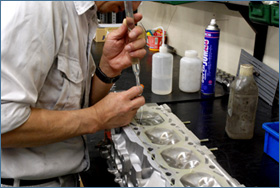
7:バルブ擦り合わせ7:VALVE FRICTION ADJUSTMENTS
 |
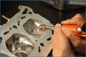
バルブラッパーにバルブをセットし、傘部のバルブシートとの当たり面にコンパウンドをつけて擦り合わせます。 これにより、バルブとバルブシートリングの密着度が上がり、圧縮漏れを防止できます。 この場合、当たり面の幅が広すぎると面圧が低下し、さらには異物を噛み込みやすくなり、逆に幅が狭いと放熱性の低下や気密性に問題が 出る場合があります。 さらには、バルブシートカットにより整えた面を必要以上に削らないように、最小限の研摩で最適な当たり面・当たり幅になるように施工します。 Lapping compound is then used to lap the valve and seat ring to chek for correct sealing and contact areas of the valve to the seat ring. The right contact area amount is then identified and the correct adjustments can then be made to optimize seal and prevent any gas leaks. If the contact area us too large then there is a risk of collecting grit and grime or developing a buildup of carbon which can damage both the valve and seatring and loose performance. If the contact area is too narrow then the force loads on the seat ring is too high and the valve will not be able to cool down efficiently as the heat cannot dissipate to the cylinder head effectively. Lapping must be done with care and with detailed attention so as not to damage the prepared seat ring and valve surface. |
8:シリンダーヘッド下面修正研磨8:HEAD SURFACE CORRECTION
 |
ヘッド全体の変形、燃焼室側面も局部的な変形、またはフライスカッター痕などを修正面研しています。 シリンダーヘッド下面を平面に整えることで、ブロックとの合わせ面の平面度を高め、燃焼ガス圧のシール性を向上させています。 The head is checked for any signs of deformation and then corrected with the mill cutter to make the appropriate corrections. This will increase the heads plane to improve sealing characteristics with a secure flat face to met will to the cylinder block. Having corrected the face of the head will help increase compression and give more power. |
9:洗浄9:WASHING
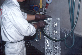 |
水穴・オイル穴を手作業で細かく洗浄し、そのあとに洗浄機による高温高圧洗浄、高圧エアによる仕上げを行います。 これら3重の工程を経て各部を徹底的に洗浄します。同時に傷・バリ・カエリなど各部の点検を実施します。 Complete cleaning of the water & oil lines is meticulously done by hand manually with each and every block with every orifice and areas checked thoroughly, Then finished off with a high pressure hot wash in a specialized machine and finally completed with a high pressure air clean in evey line,gaps and orifices. This extensive 3 stage process is time consuming but an absolute must to completely eradicate any unwanted burr and foreign material from causing harm to the internals. |
10:燃焼室容積計測・調整9:COMBUSTION CHAMBER CAPACITY ADJUSTMENTS
 |
これまでシートリングの拡大・バルブシートカット・形状の最適化と手を入れてきた燃焼室を、コンプリートヘッドのスペック設定に適した圧縮比に各気筒を揃えるために容積の調整をします。 調整量は10分の数ccとわずかなものですが、こういった細かい数値を一つ一つ正確に合わせていくことで、最終的に精度の高いスムースに回るエンジンとなっていきます。 Larger valve seats rings are fitted and adjusted,the valve seats are then cut and finally the combustion chambers are carefully calculated and adjusted to suit the target displacement on each cylinder. The engines have their cylinder compression chamber rations all adjusted to suit the target volume. Meticulous attention to detail and precsion adjustments of 0.0-0.9cc is normal in our standards to attain the optimum smooth. |
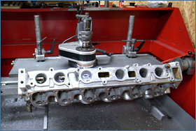
11:精密組み立て11:PRECISION ASSEMBLY
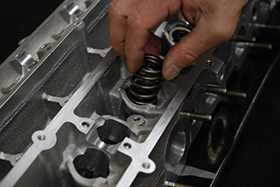 |
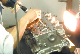
TOMEIのエンジン組み立ては精度と精密さを常に追求しているため、あえてその作業を「精密組み立て」と呼んでいます。 素材・環境・作業・管理、そのすべてに設けられた厳しい社内基準をクリアし、はじめて東名パワード製品として提供しています。 Our precision assemblies are well known throughout the years and have been our trademark. Our high standard of work has proven records on the street, track and evens to deliver results when needed most. Our stringent lebels of operations management in materials and processes reflect on our products performance throughout the years. |
COMPLETE HEAD for EJ
COMPLETE ENGINE
High RPM and high output. The parts and head tuning that are essential to achieve these goals!
PRODUCT INFO
| APPLICATION | TYPE | PARTS | P/N | JPY | NOTES | |
|---|---|---|---|---|---|---|
| EJ207/20Y | GDB C-G | With out camshaft | CPH-EJ20-S | 234012 | ¥780,000 | |
| With camshaft | CPH-EJ20-S-C | 234112 | ¥930,000 | |||
| GR/GV/VAB | With out camshaft | CPH-EJ20-D | 234022 | ¥780,000 | ||
| With camshaft | CPH-EJ20-D-C | 234122 | ¥930,000 | |||
| EJ25 | SINGLE AVCS (USDM) | With out camshaft | CPH-EJ25-S | 234032 | ¥780,000 | |
| With camshaft | CPH-EJ25-S-C | 234132 | ¥930,000 | |||
| DUAL AVCS | With out camshaft | CPH-EJ25-D | 234042 | ¥780,000 | ||
| With camshaft | CPH-EJ25-D-C | 234142 | ¥930,000 | |||
FEATURE / SPEC
| タイプTYPE | カムシャフト無With out camshaft | カムシャフト有With camshaft | ||||
|---|---|---|---|---|---|---|
| 品番P/N | 234012/234022 | 234032/234042 | 234112 | 234122 | 234132 | 234142 |
| ベースエンジン型式BASE ENGINE | EJ25 | EJ207 | EJ207/20Y | EJ257 | EJ25 | |
| 約50.0ccapprox.50.0cc | 約52.5ccapprox.52.5cc | 約50.0ccapprox.50.0cc | 約52.5ccapprox.52.5cc | |||
| バルブVALVE | ||||||
| バルブスプリングVALVE SPRING | ||||||
| バルブスプリングリテーナーVALVE SPRING RETAINER | ||||||
| バルブスプリングシートVALVE SPRING SHEET | ||||||
| バルブガイドVALVE GUIDE | ||||||
| バルブシートリングVALVE SHEET RING | ||||||
| カムシャフトCAM SHAFT | TOMEI IN 250-9.60 EX 256-9.80 S-AVCS |
TOMEI IN 260-9.80 EX 256-10.80 D-AVCS |
TOMEI IN 260-9.80 EX 264-10.00 S-AVCS |
TOMEI IN 260-9.80 EX 264-10.00 D-AVCS |
||
| バルブリフターVALVE LIFTER | STD | |||||
概要Overview
実施する精密加工BUILD PROCESS
1:バルブガイド入替え1:VALVE GUIDE REPLACEMENT
|
純正バルブガイドを抜くために、シリンダーヘッドを約200度まで加熱します。 アルミ合金製のシリンダーヘッド と焼結合金製の純正バルブガイドの熱膨張率の差を利用することで、純正バルブガイドを抜きます。 TOMEIバ ルブガイドを挿入する際もシリンダーヘッドを同様に加熱し、さらにバルブガイドを液体窒素で約-200度まで 冷却し、この400度近い温度差による材質の熱膨張率の差を利用しセットします。 もし、液体窒素を使用せず、 充分な温度差と膨張差を得られないまま無理に挿入すると、バルブガイドの穴を傷つけたり、バルブガイド自 体が変形し、オイル下がりや、クリアランス不足によるバルブの焼き付きを招きます。 The cylinder head is heated up 200℃ so that the stock valve guides can be removed. The cylinder heads that are made from aluminum alloy when heaated expands more than the materials that the valve guides are made from thus making it easy to remove when heated. The TOMEI Valve guides are also inserted in the same way but the Valve Guides are frozen in liquid nitrogen with to bring down the valve guides temperatures to -200℃ and with 400℃ difference it is then made possible to insert the new Valve guides into the Cylinder Head with ease and safely. If liquid nitrogen is not used then damage can be caused during the removaland re-instrallation of the valve guides as the gap will not be wide enough to fit the new valve guides into the head. This can also cause the deformation of the valve and create gaps which can lead to oil leaks. |
2:バルブシートリング内径拡大2:VALVE SEAT RING INTERNAL DIAMETER ENLARGEMENT
|
オーバーサイズバルブの採用に合わせ、バルブシートリングの内径を拡大します。 ただ単純にバルブ径に合 わせて拡大するのではなく、オーバーサイズバルブで得た有効吸排気面積を損なうことなく吸排気ポートにスムースにつなげ、吸排気の流れを考慮した角度を採用しています。 また、強度の維持にも留意した仕上げを行っています。 The inner diameter of the valve seat ring is enlarged to accommodate for the oversized valve. There is much more involved than just simply enlarging the valve size and the ring seats. Much consideration in redesigning and experience is vital so not to risk weakening the structure and or hindering performance. It us also involved to the aerodynamics of the untake and exhausts ports with all angles and flow dynamics taken into consideration. |
3:バルブシートカット3:VALVE SEAT CUT
|
バルブ当たり面の幅・位置・テーパー角度などをバルブ・燃焼室形状・ポート形状に合わせた最適な形に整えます。 これによりバルブとバルブシート間の密着性を上げ、圧縮圧力が逃げるのを防ぎます。 この加 工は エンジン機 種それぞれに燃 焼 室・バルブ・ポートのサイズ・形状が異なるため、それぞれに膨大なテストを実施し、最適な形状を導き出しました。 Each valves seat width,position,taper angle and the surface condition is addressed to maximize the aerodynamics of the mouth from the ports & valve tothe combustion chamber and back to the exhaust port. Each seat is cut to suit each valves position,tapered angle with all surface angles arranged to optimize port flow to the valve and to the combustion camber. By increasing the sealing properties of the valve to the valve seat than more accurate compression can be maintained from preventing any pressure from escaping through any gaps. This process is extremely time consuming to find the optimum design and setup to suit each engine with each engines design characteristics and to suit the engines purpose. |
4:燃焼室形状の最適化4:OPTIMIZING THE COMBUSTION CHAMBER
|
純正の燃焼室にはバルブシートリング周りに、製造時の段付が残されたままになっています。 この段付が吸排気の大きな抵抗になるため、これを削り取り、整えます。 特にマルチバルブのエンジンでは燃焼室の面積に対して、バルブ面積の割合が大きいため燃焼室の壁が近く、これも抵抗になります。 燃焼室全体を段付修正も含め て削ることで、バルブから燃焼室の壁までの距離を増やし、さらにはシリンダーとのつなぎ目の部分もスムースにでき、吸排気の有効な流路面積を確保しています。 The valve seat rings surrounding area may have some imperfections which also affects the combusition chambers volume as it was designed from factory. So by targeting this area the flow can be optimaized which will also reduce any signs of flow disruptions. The multivalve engine designs which tend to have a limited area and the combustion chamber walls can cause resistance and limitations. A vital process is to deburr aby casting imperfections on the port area just above the seat ring. These factory casting imperfections hinders the air flow to the combustion chamber which restricts performance. Smoothing this area is an absolute must and extra care and attention is taken into account for the airflow and dybanucs of this area. |
5:ポートの段付修正5:PORT STEP CORRECTION
|
バルブシートリングと吸排気ポート間の段付を修正し、燃焼室形状の最適化と合わせて吸排気行程における有効な流路面積を確保しています。 Correcting the valve sheet rings helps optimize the combustion chamber shape and makes the flow characteristics much better on the Intake and Exhaust side. |
6:バルブスプリングセット長合わせ6:VALVE SPRING SET ADJUSTMENTS
|
エンジンを低回転からトップエンドまでスムースに回すためには、動弁系の軽量化はもちろんのこと、バルブスプリングのセット長を合わせることも必要になります。 そのためにはバルブシートカット→バルブの突き出 し量計測→バルブスプリングシート調整を経てバルブのセット長を合わせます。 これにより、バルブスプリングの設計性能が発揮できることになり、セット荷重も整うことになります。 The valve springs will need to be upgraded to help keep a good balance for low and high engine speeds. The added weight reduction woll help the valve train assembly. The key points are the set load properties of the valve spring and also the weight reduction. Checking the valve length extention to measure the valve sheet cut,and then setting the valve length through the set of valve spring sheet adjustments. This process will show the valve springs design efficiency which also means that the load is then set. |
7:バルブ擦り合わせ7:VALVE FRICTION ADJUSTMENTS
|
バルブラッパーにバルブをセットし、傘部のバルブシートとの当たり面にコンパウンドをつけて擦り合わせます。 これにより、バルブとバルブシートリングの密着度が上がり、圧縮漏れを防止できます。 この場合、当たり面の幅が広すぎると面圧が低下し、さらには異物を噛み込みやすくなり、逆に幅が狭いと放熱性の低下や気密性に問題が 出る場合があります。 さらには、バルブシートカットにより整えた面を必要以上に削らないように、最小限の研摩で最適な当たり面・当たり幅になるように施工します。 Lapping compound is then used to lap the valve and seat ring to chek for correct sealing and contact areas of the valve to the seat ring. The right contact area amount is then identified and the correct adjustments can then be made to optimize seal and prevent any gas leaks. If the contact area us too large then there is a risk of collecting grit and grime or developing a buildup of carbon which can damage both the valve and seatring and loose performance. If the contact area is too narrow then the force loads on the seat ring is too high and the valve will not be able to cool down efficiently as the heat cannot dissipate to the cylinder head effectively. Lapping must be done with care and with detailed attention so as not to damage the prepared seat ring and valve surface. |
8:シリンダーヘッド下面修正研磨8:HEAD SURFACE CORRECTION
|
ヘッド全体の変形、燃焼室側面も局部的な変形、またはフライスカッター痕などを修正面研しています。 シリンダーヘッド下面を平面に整えることで、ブロックとの合わせ面の平面度を高め、燃焼ガス圧のシール性を向上させています。 The head is checked for any signs of deformation and then corrected with the mill cutter to make the appropriate corrections. This will increase the heads plane to improve sealing characteristics with a secure flat face to met will to the cylinder block. Having corrected the face of the head will help increase compression and give more power. |
9:洗浄9:WASHING
|
水穴・オイル穴を手作業で細かく洗浄し、そのあとに洗浄機による高温高圧洗浄、高圧エアによる仕上げを行います。 これら3重の工程を経て各部を徹底的に洗浄します。同時に傷・バリ・カエリなど各部の点検を実施します。 Complete cleaning of the water & oil lines is meticulously done by hand manually with each and every block with every orifice and areas checked thoroughly, Then finished off with a high pressure hot wash in a specialized machine and finally completed with a high pressure air clean in evey line,gaps and orifices. This extensive 3 stage process is time consuming but an absolute must to completely eradicate any unwanted burr and foreign material from causing harm to the internals. |
10:燃焼室容積計測・調整9:COMBUSTION CHAMBER CAPACITY ADJUSTMENTS
|
これまでシートリングの拡大・バルブシートカット・形状の最適化と手を入れてきた燃焼室を、コンプリートヘッドのスペック設定に適した圧縮比に各気筒を揃えるために容積の調整をします。 調整量は10分の数ccとわずかなものですが、こういった細かい数値を一つ一つ正確に合わせていくことで、最終的に精度の高いスムースに回るエンジンとなっていきます。 Larger valve seats rings are fitted and adjusted,the valve seats are then cut and finally the combustion chambers are carefully calculated and adjusted to suit the target displacement on each cylinder. The engines have their cylinder compression chamber rations all adjusted to suit the target volume. Meticulous attention to detail and precsion adjustments of 0.0-0.9cc is normal in our standards to attain the optimum smooth. |
11:精密組み立て11:PRECISION ASSEMBLY
|
TOMEIのエンジン組み立ては精度と精密さを常に追求しているため、あえてその作業を「精密組み立て」と呼んでいます。 素材・環境・作業・管理、そのすべてに設けられた厳しい社内基準をクリアし、はじめて東名パワード製品として提供しています。 Our precision assemblies are well known throughout the years and have been our trademark. Our high standard of work has proven records on the street, track and evens to deliver results when needed most. Our stringent lebels of operations management in materials and processes reflect on our products performance throughout the years. |
